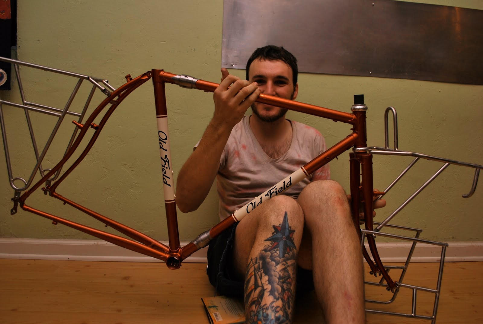
finalized the geometry for Arnold's track frame. He wants a frame with steep head and seat tube angles(both 74 degrees), short rake(30mm), but a standard road bottom bracket drop(70mm). He currently rides a Surly steamroller, so the frame is designed to have the same fit.
here is a quick tutorial on how i draw a frame to full scale, im sure other builders do it differently. some builders have access to a printer which can print a full size image, which would be nice.
things you will need:
-a large piece of paper (i use news print that is free from the local newspaper, it is large enough to draw any frame, although its quite thin)
-a meter(yard) stick with metric
-pencil(i use mechanical pencils to get a finer line)
-a protractor(a machinist protractor works best, but the cheap ones from math class work)
- a vernier caliper with metric( dial and digital work too, but i prefer vernier)
step one
Near the bottom of the page make a long straight line that is at least as long as the wheelbase of the frame from the rear dropouts to the front dropouts) this is your
wheel axle centerline.
then measure and mark the bottom bracket drop below this line in at least 3 places. connect the dots and this will give you a parallel line with your axle line. this represents your bottom bracket drop and i use it for some reference measurements for my Bringheli frame fixture.
step two
mark your bottom bracket on the lower line, i also have a neat circle making tool which you can get at an art supply store. for lugged frames, i use the circle that is the internal diameter of the lugged bottom bracket shell. for non lugged frames i use the circle that marks the outer diameter of the bottom bracket shell. make sure when you draw in the bottom bracket you give enough room to draw your chainstays on the one side and the front end of your bike on the other.
You can now draw the seat tube angle with your protractor. then extend the line with your meter stick. this is your seat tube centerline
step three
mark your seat tube height(this one is 53cm from the center of the bottom bracket to the center of the top tube) and you can draw in your top tube. this can be done in two ways: you can use the protractor by keeping the same angle you used for the seat tube angle and flipping it over to mark the top tube. if you remember geometry class, if your top tube is parallel, then the angle will be the same as the angle at the bottom bracket. then you can draw your top tube off of this line. the other method. i measure the imaginary perpendicular line from top tube to the bottom bracket line and then use this measurement to mark the line for the top tube. i use this method and then check the angle with the protractor to make sure its exact. its a good means to double check your work.
step four
mark your headtube point on the top tube centerline. use your protractor to draw your headtube angle and use your ruler and draw a line all the way to the axle line. you can check the headtube line against the axle line and you should get the same angle(if your headtube angle is supposed to be 74 degrees, then the angle at the axle line should be the same)
step five
measure the fork rake distance from the headtube line/axle line junction along the axle line and mark it. i like to put 2 lines, one perpendicular to the axle line and one parallel to the headtube line. the line just needs to be a few inches long for reference purposes. now you have your fork dropout mark.
step six
from the fork dropout mark you can draw in your imaginary wheel. figure out the radius of your maximum wheel size you want to use(this frame will have 700c x28 tires and the radius is around 340mm). i draw it by hand, but there are a number of tools to make large circles. i just measure from the dropout mark out and make a number of marks and connect the dots. i then mark my desired fork crown/tire clearance with a line perpendicular to the headtube line, then make another line like it for the headset lower stack height(technical information for common headsets is readily available, you can also measure the headset with a caliper) then the last line marking the bottom of the frames headtube
step seven
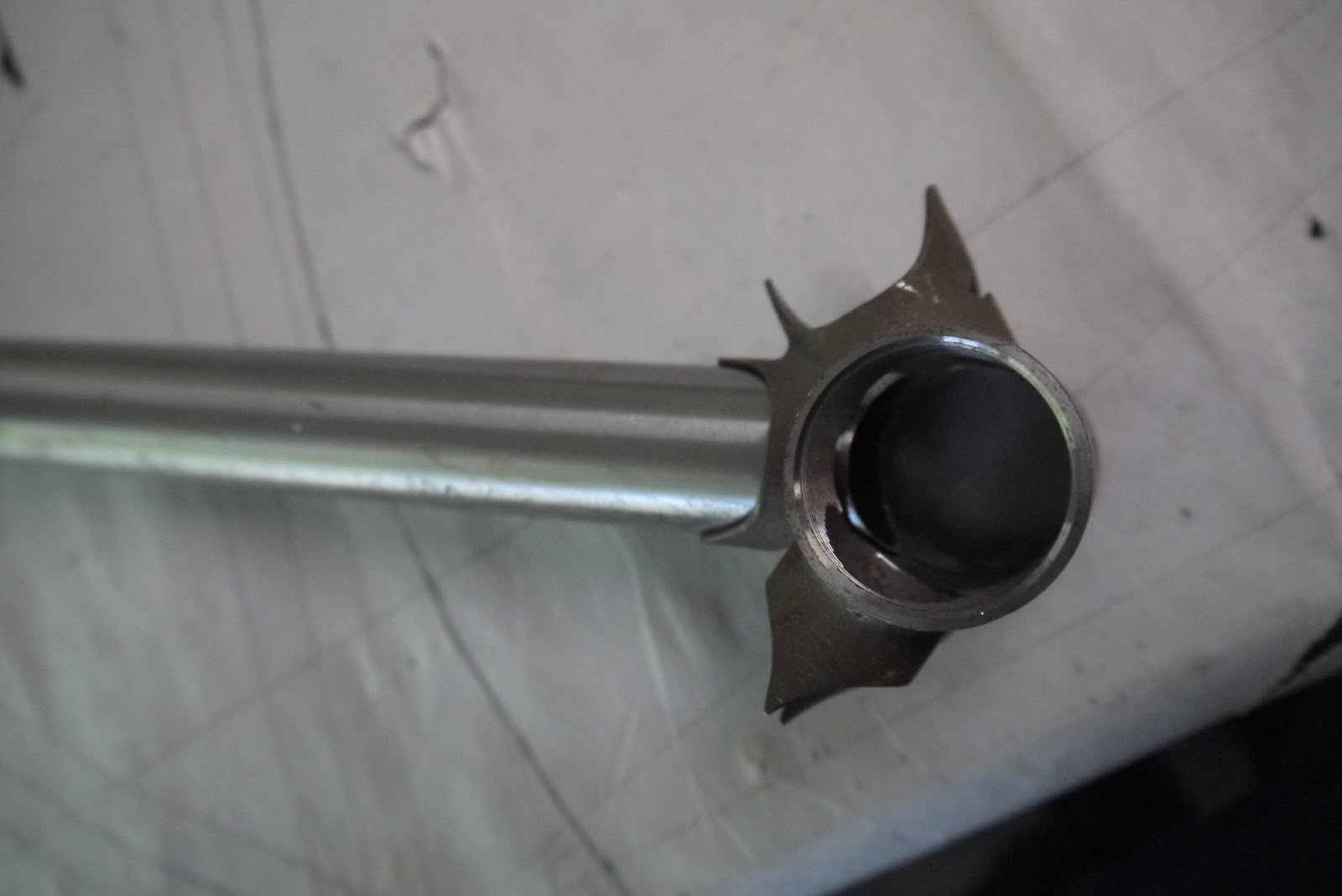
now you have to add the tube outside diameter for the headtube. this lugged headtube is 31.7mm. i use the caliper to measure half that distance from the headtube centerline and do so on both sides and a few spots along the fore mentioned line. then i connect the dots and go back and check to make sure its square and the right diameter(this is crucial)
step eight
now that the headtube is drawn in, we can mark the downtube. if its a lugged frame, you must measure the backside of the lower head lug to figure out the junction of the head and downtube. if its a welded frame there is a lot more play here and you can put this junction where you deem best. mark the lower downtube headtube junction.
i have a few different yard sticks that i have found that are exactly the width of the different downtubes(and seat tubes) i use. this makes it very easy to draw the downtube. i put a notch in the end of the stick to reference its center point and line that up with the center of the bottom bracket. then i line the other side of the straight edge with the downtube/headtube junction mark i just made and then draw the downtube outer lines(then you can go back and draw in the centerline for the downtube)
after that i do the same thing for the seat tube(this frame uses standard gauge tubing, so the seat and down tubes are the same diameter). for the seat tube i put marks for the width of the tube on either side of the seattube centerline then i can easily locate the center point and draw the lines for the tube.
step nine
do the same thing for your top tube and you are done. if you dont have a straight edge that is the width of the tubing you intend to use, then you have to draw the lines by measuring half the diameter of the tubing from the center line of the tube. for instance, if you are using a 25.4(1 inch) diameter top tube, then you need to make marks 12.7mm( above and below) along the center line and then use the straight edge to connect the dots. this method can be used for all of the tubes.
now your front triangle is done. its important that you check all your measurements because this drawing will be the reference for cutting your tube angles and lengths
step ten
drawing the rear triangle is not as important in my opinion. at least for the way that i build frames(i also use bikeCAD along with hand drawing, so i know my designs are sound before putting them to paper), but i like to mark the rear dropouts and wheel diameter to get an idea of what it will look line and they are helpful in locating braze ons, bridges, where to cut the stays and figuring the angle of the dropouts.
measure from the bottom bracket to the point on the axle line where you want your drop out, then from this point you can draw in your wheel and the seat and chainstays.
final notes
i draw my frames facing left, but you can do the same thing in the other direction, this is because of the Bringheli fixture i currently use.
the benefit of drawing the frame in this order is to figure out the headtube length and fork length. if you already know the fork you want you can change the order you draw the frame.